Shielded Cable & Wiring
EMI SHIELDING: UNDERSTANDING THE DIFFERENT TYPES
Electrical noise of any type can disrupt proper operation of other equipment and should be shielded to combat the electromagnetic interference effects in cables. Insulation protects a cable mechanically from scraps and abrasion and
environmentally from moisture and spills. But insulation is transparent to electromagnetic energy and offers no protection. Shielding is needed to combat the effects of EMI.
SHIELD TYPES
Served shields are spiral-wound groups of small-gauge wire strands surrounding the insulation of the conductor(s). They are easy to unwind and terminate but are prone to be relatively inductive because they are coiled around the
cable. They are the most flexible of shielded cables and are often used in audio applications. Served shields are usually soldered, or crimped to a lug or termination post.
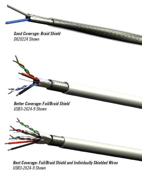
Braided shields are woven over and under one another to form a tight but flexible cylinder of wires. This may result in the need to unbraid or loosen the weave in order to terminate it, though it lends itself to easy coaxial connector termination, and preserves the shield all the way to the connector body. 95% coverage is not unusual on high-quality cables.
Most commonly, braids are formed of groups of small-gauge wires known as “carriers.” These are laid side-by-side, a ribbon-like multi-path conductor. Braids can also be a “strip braid,” using solid ribbons of conducting material, providing a more uniform inner surface to a coaxial conductor. This is an advantage at very high frequencies, and if it is combined with other shield designs, forms a very effective EMI barrier.
Braided coax shields are usually terminated in the field by crimping or clamping, and are occasionally soldered, or are terminated with a heat-shrink shield pigtail. This latter approach is common in aircraft wiring harnesses. Braided
non-coax shields can be soldered if the conductors within are dressed to exit the shield through an opened space in the braid, or can be terminated with a heat-shrink shield pigtail. Foil shields consist of a metalized flexible plastic (Mylar, polyimide, etc.) wrapper, spiraled around the conductor(s). The metalized layer is very thin — on the order of .0003 inch. Foil coverage can be effectively 100%, although its resistance is far greater than the other shield described here, and thus its ability to shunt noise is limited. For this reason, EMI protection is best if foil shields are used in combination with braided (better conductors) shields.
Foil shields, since they are usually aluminum, are necessarily crimped, though some are combined with a “drain wire”, which makes contact with the foil and may be soldered. Solid shielding comprises a metal tube, rigid or semi-rigid
— usually copper or aluminum — surrounding the dielectric and center conductor. Semi-rigid coaxial cables of this design can be formed by hand, though tube bending tools are recommended, especially for smooth tubing. (Larger cables may incorporate corrugated-like tubing.) Coverage is 100% and resistance is low. There is no better shield. Common applications of solid-shielded types include short, fixed coax jumpers
Solid Shields are usually soldered or clamped. Soldering aluminum solid shields is impractical. Shield Coverage depends upon design and level of quality—and ranks from poor to perfect. Not every application justifies the costly pursuit of perfection. The degree of need depends on the frequencies of concern and the noise susceptibility (or signal strength, for shield containment roles) of the circuit. Shield Termination should not be taken lightly, since more problems crop up at connectors than any other part of a cable. In all cases, shield integrity is best if the shield is intact (no broken strands or flaking foil) and prepared for maximum contact with the connector. This includes cleanliness. The
connector manufacturer’s instructions deserve serious attention.
SHIELD EFFECTIVENESS
Regardless of its construction, a shield will be only as immune to induced noise as its effectiveness provides. This means that the shield will “intercept” and/or deflect magnetic or electrical fields which interfere with the signal needed.
Frequency, amplitude and physical spacing are factors. Management of the problems of noise — induced, or as a source — includes shielding.
Shielding effectiveness is the ratio of incident wave (source) field strength to the allowable field strength. It is customarily expressed in dB. Shields can function as reflectors or absorbers (shunting to ground) of radiated electrical or magnetic fields. Since in avionic systems we commonly concern ourselves with rampant RF, we’ll focus on properties of shields which are most effective at high frequencies.
Reflection of unwanted signals can be likened to a mirror. The surface of the shield is the operative element, and in truth, it is the conductivity of this surface — the skin — which plays the most important role in high-frequency applications. This is one excellent reason for the silver plating on the shielding wires used in high-performance cables.
Beneath the reflective surface, the conductivity of copper lends itself well to absorption, draining the interfering signal to ground. While copper is not as effective as steel in absorption of frequencies below 1GHz, it is a more effective
shield, overall, if both absorption and reflection are taken into account.
As the shield is designed, it is not necessarily true that layer upon layer of shields are any more appropriate than simple well-made shields may be. Sometimes, however, layering can block openings (interstices — the intersections of braid elements), important because even a pinhole is a window to noise at high frequencies.
Shields are beneficial in containing interference as well as protecting from it, serving to reduce the effects of noise which might be induced in neighboring cables, or bundles of wires.
Testing for leakage in coaxial cable shields tells the story of how to cope with the RF “traffic jam” that is now more invasive than ever anticipated. It is given that 100% shielding, such as provided by rigid or semi-rigid cables, is ideal. What is less evident is that MIL-C-17 coaxial cables are far off the ideal. Perhaps this is why PIC’s multi-layer low-loss cables are increasingly accepted — for perhaps other reasons, too, such as loss or weight — but bring the substantially improved leakage factors along as well.
Network analyzer testing of PIC coax designs—incorporating the silver-coated inner strip braid, the metalized polyimide 100% wrap, and the tight wire outer braid—show performance that approaches that of semi-rigid cables.
Comparison testing shows leakage on the order of 55-75dB for RG142, and 85-90dB for PIC S44193. Semi-rigid RG402 is 110dB. (These are all cables whose other characteristics are roughly comparable.)
To summarize, shielding usually just works. But if EMI problems crop up—and they will when you least expect them—it is always important to consider the quality of the cable as a first line of defense. What’s the importance of all this? In the complex RF environment of an ever-growing rat’s nest of signals, often bundled together and “sharing” noise, better shielding improves signal integrity and system reliability.