Skip to Content

Maximize Your Connections with High-Quality Cables

Main Content

Testing Ensures Quality Cable But Limits Length

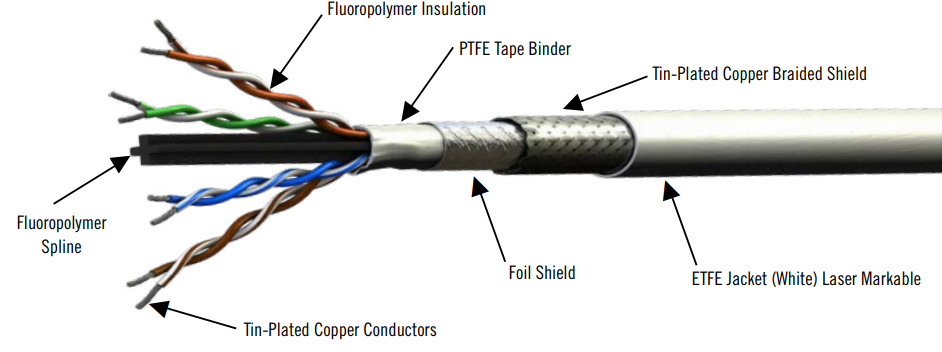
As engineers know all too well, a cable is much more than a convenient way of connecting two electronic devices: it is also a complex passive circuit with its own resistance, capacitance, and inductance. A typical cable in a demanding aerospace or military application, such as the 10G Base-T Cat 6a Ethernet cable shown in Figure 1, contains multiple parts.

Although customers might wish for a cable of unlimited length, two reasons limit the spool length of real-world products: Manufacturing materials and practical manufacturing constraints. To ensure the best quality cables, multiple tests are performed to verify the cable’s effectiveness.


parts of cable

Common Cable Manufacturing Challenges

The finished cable assembly must meet the mechanical and electrical performance requirements for the end application. Each part of a cable represents a potential point of failure, which can occur at any point along its length. If testing detects a failure, the flawed section of the cable is removed and the two sections are retested. Complex cables have more potential failure mechanisms and shorter maximum cable lengths.

As depicted in Figure 1, kinks or stray wires in the primary conductors can cause issues such as out-of-spec outer diameter (OD), and electrical issues like high attenuation or return loss. A strand poking through the wire insulation can also cause a spark test failure.

Many factors can result in a primary conductor insulation failing the spark test such as contaminants (FOD), the processing of individual primary wire insulation, which can vary slightly depending on equipment setup, the operator, and batch (lot) of fluoropolymer and things like daily temperature.

The outer braid shield is where a cable braid consists of numerous small wires, each on an individual tiny bobbin or spool. The wire braid shield is applied after (over) the foil braid. If a wire breaks during the braiding operation, the cable must be cut at that point to replace the bobbin before continuing the braiding process. A new spool is then started; this also applies if an individual bobbin runs out.

The overall jacket undergoes a 100% spark test that looks for small imperfections in the overall cable jacket. The outer braid is grounded and the cable is run through a bead tester that has a high voltage (typically 3.0 kV) applied to it. Any microscopic pinhole or flaw in the cable jacket will cause a spark, resulting in an automatic shutdown of the test and the removal of the flawed section.

The final test ensures that the finished cable meets its specified electrical performance requirement. For example, a CAT 6a (four-pair) Ethernet cable must pass Category 6a testing, which includes near-end cross-talk (NEXT) and insertion loss. If the cable fails any requirement, the cable is retested to isolate the failure to a certain area of the cable. In that event, the section is removed (cut out) and the cable is retested. It is possible that the entire spool could be suspect and ultimately destroyed.

Common Cable Manufacturing Challenges

The finished cable assembly must meet the mechanical and electrical performance requirements for the end application. Each part of a cable represents a potential point of failure, which can occur at any point along its length. If testing detects a failure, the flawed section of the cable is removed and the two sections are retested. Complex cables have more potential failure mechanisms and shorter maximum cable lengths.


POTENTIAL MATERIAL FLAWS

Primary Conductor

At times, a slight kink in the conductor or a stray wire in a stranded conductor can cause issues for instance, the outer diameter (OD) becoming out of spec, creating electrical issues such as VSWR, Capacitance, Return Loss or even a spark test failure with a strand poking thru the insulation. When these defects are detected, the defective areas are cut out of the cable run resulting in shorter cable runs or spools.

Primary Conductor Insulation

There is always the possibility of contaminants such as dirt, debris, and foreign object debris (FOD). Also, the processing of an individual primary wires insulation can slightly vary depending on the equipment set up, the operator, batch (lot) of Fluoropolymer, even the temperature of the day can have an effect on the final primary wire. Many factors can result in a primary conductor insulation failing the spark test such as dirt, debris or other contaminants (FOD) as well as the processing of individual primary wire insulation. Variations in equipment setup, the operator, batch (lot) of fluoropolymer, or even daily temperature can impact the primary wire insulation.

Electrical Performance

All cable is final tested to its specified electrical performance requirement. For example, a CAT 6a (4 pair) Ethernet cable must pass Category 6a testing, which includes Near End Cross Talk (NEXT), Insertion Loss, etc. If the cable fails any requirement, the cable is retested to isolate the failure to a certain area of the cable. In that event, the section is removed (cut out) and the cable is retested. It is possible that the entire spool could be suspect and ultimately destroyed.

Inner Foil Shield

The inner foil shield is typically made of an aluminum/mylar or aluminum/polyimide composite. The available footage of this “foil pad” is limited: when the pad of foil runs out, the manufacturing operation is halted, the foil pad is replaced, and the foil process starts over with a new cable spool.

Outer Braid Shield

The outer braid shield is comprised of numerous small wires, each on an individual tiny bobbin or spool. The wire braid shield is applied after (over) the foil braid. If a wire breaks during the braiding operation, the cable must be cut at that point to replace the bobbin before continuing the braiding process. A new spool is then started; this also applies if an individual bobbin runs out

Overall Jacket

The overall jacket undergoes a 100% spark test that looks for small imperfections in the overall cable jacket. The outer braid is grounded and the cable is run through a bead tester that has a high voltage (typically 3.0kV) applied to it. Any microscopic pinhole or flaw in the cable jacket will cause a spark, resulting in an automatic shutdown of the test and the removal of the flawed section.

MANUFACTURING LIMITATIONS

In addition to failures caused by the cable elements themselves, the realities of the cable manufacturing process can lead to other issues that limit the practical length of a spool. Some of these include twinning pairs, which is where a one-pair cable consists of two single primary wires twisted together. The two single wires come from two spools of different lengths. When one spool runs out, the twinning operation is stopped, causing a spool break. The empty spool is replaced, and the twinning process resumes. This is an ongoing process, especially when combining two or four pairs in Ethernet cables such as a CAT 5e or CAT 6a.

END RESULT: QUALITY CABLES

Although an unlimited cable length might be preferred, all of these factors together limit the length of a spool and are common to all manufacturers and all multi-element cable types.

PIC Wire & Cable strives for perfection during our manufacturing process and post-manufacturing tests, ensuring that every foot of cable that ships is considered a quality, reliable, certified product.