Velocity Factor in Cables
VELOCITY FACTOR IN CABLES
In theory, electrical signals move at the speed of light. Cables only slow them down. The ratio of actual speed to the speed of light is known as the velocity factor, or Velocity of Propagation (VOP), expressed as a percentage of the speed of light in free space.
This slowing effect is almost entirely caused by the dielectric material; in coaxial cables, the insulation between the shield and the center conductor. For a closed-cell foam dielectric, for example, the VOP may approach 90%, meaning that a signal will travel at 90% of the speed of light. For solid Teflon®, the VOP is typically about 70%.
(These figures can differ according to specific formulation of the material. They are also subject to variation depending on the construction of the cable.)
What effect does the VOP have? After all, 70% of the speed of light is still pretty fast! Fact is, in some avionic and other electronic applications, speed and delay are critical factors and need to be measured with precision.
The delay from one end of a cable to the other is inversely proportional to the VOP: the lower the VOP %, the longer the delay.
This can be important in relative signal timing, for navigation systems, for example. Delay is independent of frequency. In effect, it is the defining factor of the electrical length of a wire or cable.
Published literature often lists delay among the characteristics of cable. If so, it’s a simple matter to calculate the delay for a specific length of cable based on the “ns/ft” value. But it is also practical to calculate delay using the VOP and the following formula:
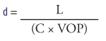
...or, more practically,
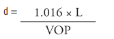
where: d = Delay in nanoseconds
L = Length of the cable in feet
C = Velocity of light in free space
VOP is expressed in percent
As a guideline, Table 1 lists VOP, dielectric constant, and delay for some of the common cable dielectric materials, along with a few less common materials, included for your amusement.
| Material | @ 1.0 GHz | VOP | DELAY |
|---|---|---|---|
| TYPICAL INSULATION MATERIALS | |||
| Cellular TFR | 1.38 | 85% | 1.2 |
| FEP | 2.1 | 69% | 1.47 |
| Silicone | 3.6-2.1 | 53-69% | 1.92-1.47 |
| TFE | 2.1 | 69% | 1.55 |
| Polyethlene | 2.3 | 66% | 1.55 |
| PVC | 8.2-3.0 | 35-58% | 2.9-1.75 |
| Nylon | 4.5-3.6 | 47-53% | 2.16-1.92 |
| NON-TYPICAL INSULATION MATERIALS* | |||
| Snow (Fresh) | 1.2 | 91% | 1.1 |
| Vaseline | 2.2 | 68% | 1.49 |
| Beeswax | 2.8 | 60% | 1.69 |
| Ice | 3.2 | 56% | 1.8 |
| Glass | 8.2-3.8 | 35-51% | 2.9-2.0 |
| Water (Distilled) | 82 | 11% | 9.2 |
| *Theoretical values if cables were constructed of these materials. e = dielectric constant |
|||
Table 1. Electrical parameters of various materials
Table 2 carries this into PIC coaxes and a few RG- types.
| Part No. | @ 1.0 GHz | VOP | Delay |
|---|---|---|---|
| PIC CABLES | |||
| S22089 | 1.45 | 82.5% | 1.2 |
| S33141 | 1.56 | 80.5% | 1.3 |
| S44191 | 2.0 | 69.5% | 1.5 |
| S44193 | 2.0 | 69.5% | 1.5 |
| S46191 | 2.0 | 70% | 1.5 |
| S55122 | 1.4 | 84.5% | 1.5 |
| S67163 | 1.56 | 80% | 1.2 |
| S86208 | 1.6 | 80% | 1.3 |
| S88207 | 1.56 | 80% | 1.3 |
| V75268 | 1.4 | 80% | 1.3 |
| V76261 | 1.56 | 80% | 1.3 |
| SELECTED MIL-C -17 CABLES | |||
| RG142, RG400 | 2.1 | 69% | 1.47 |
| RG214 | 2.3 | 69% | 1.54 |
| RG393 | 2.1 | 69% | 1.47 |
| RG58 | 2.3 | 69% | 1.54 |
Table 2. Electrical parameters of center conductor insulation of coaxial cables.
Delay is a critical factor in determining the bearing of transponder signals received by a directional TCAS antenna. But the figure of merit here is the absolute phase angle of the cable at the specified frequency.
Wavelength & VOP
At microwave frequencies (TCAS and transponders operate near 1000 MHz), a single nanosecond (a billionth of a second) is an entire wavelength. TCAS II tolerates one such wavelength (360°) of mismatch among the four upper or lower directional antenna cables, and some TCAS I processors require even greater precision than that. Note that such phase-matching requires not only that the waves coincide in pattern with one another from cable to cable but that they must do so within the very same wave. (See Figure 1.) Thus both phase and delay measurements are important.
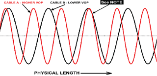
Figure 1. Relative physical length. NOTE: Cables A & B are identical length, and their phase angles are equal. However, because of different VOP’s, they have unequal electrical length. This illustration shows them “slipping” a full cycle at some point – which could have been seen with accurate delay measurement.
At 100% VOP, the physical wavelength at 1000 MHz (1.0 GHz) will be 11.80 inches. This can be proportioned according to the cable’s actual velocity factor, as well as other frequencies.
A practical formula is:
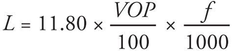
Or, reduced,
![]()
where:
L = Physical length in inches
VOP expressed in percent
f = Frequency in MHz
It needs to be understood, however, that even with the relatively uniform VOP figures in a given cable type, physically measuring them by the inch for phase-matching is no assurance of an accurate match. This is because actual VOP is not always exactly the published figure, nor can it be considered perfectly uniform, even within a single production run of cable. Variances are apt to be more pronounced in cables having high VOP’s. Only test equipment which measures electrical length with precision can verify meeting stringent standards such as required for TCAS directional antennas.
PIC produces cables which meet and exceed the requirements established for TCAS and other RF systems. Precise testing is performed to assure that crucial timing and phase- matching requirements are met.
A related Issue: Dielectric Constant
This is a property of the material itself — independent of dimensions — but is an important factor in determining VOP and delay.
The word electric derives from the Greek elektron, which translates to amber. However, amber is an insulating material and is known to produce an electric charge when rubbed. And so even though we think of electric as inferring the flow of electrons (current), we now know that the term comes from some ancient insulator (which has even been known to entomb prehistoric insects. But that’s another story — already made into a hit movie or two.)
The prefix di– infers the effect of preventing this flow. A dielectric (amber would qualify) then, is a barrier — an insulator — separating positive and negative electric charges from one another, preventing direct current flow. This action is typified by a capacitor.
In a cable, the dielectric is defined as the non-conducting plastic or rubber (or even air) which insulates a conductor from others.
No conductor material is perfect and the same is true of insulation materials. There are superconductors, special alloys which, in a very low temperature environment, actually do exhibit zero resistance. A perfect vacuum is also an absolute, but is as yet unattainable. What about making cables using a perfect vacuum as the insulation medium? It’s even more impractical than superconductors.
So, in the real world, while we might quantify absolutes without practical access to them, we can at least relate to them by a ratio. Thus defines the dielectric constant (electrical symbol  ) — the ratio of a material’s dielectric (charge storage) quality to that of a perfect vacuum. A perfect vacuum is valued at 1.0. All other materials have a greater value of .
The dielectric constant figures into determining characteristic impedance, loss, capacitance, cutoff frequency and velocity of propagation of coaxial cables.
For example, the dielectric constant of solid PTFE (as used in RG142 and RG393) is nominally 2.1. This means that it will store about twice the charge as a vacuum, or, put another way, roughly doubles the capacitance. PIC’s S33141 low-loss coaxial cable employs a dielectric with an ? of about 1.8. It is lighter and thinner but electrically equivalent to RG393, and the dielectric constant is one reason why. Tables 1 & 2 above list these details.
The lower the dielectric constant, the lower the loss, the lower the capacitance, the higher the velocity of propagation — a cable which approaches the ideal. But then we’re talking superconductors with a vacuum for insulation, or at least we are venturing into currently impractical materials.
Some formulas for determining cable parameters related to the dielectric constant are shown below:
Impedance in ohms —
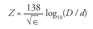
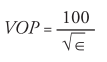
Velocity of Propagation (expressed as a % of the Speed of Light) —
Capacitance in pF/ft —
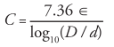
For the equations above,
D = Inside diameter of shield (inches)
d = Outside diameter of center conductor (inches)
= Dielectric constant
Calculating VSWR and loss, while the dielectric constant is a factor, is not as straightforward. For VSWR, it is also necessary to establish the reflection impedance and, for loss, the stranding and braid factors — all this being part of the cable design and engineering process.
The dielectric constant is not the only measure of quality of a cable; cellular polyethylene has an as low as 1.4, but it is rated at a lower temperature. MIL-spec coaxes using polyethylene dielectrics (such as RG58 and RG214) customarily also have PVC jackets and are, therefore, unacceptable for aircraft applications because of smoke and fire concerns.
But some newer techniques and chemistries have developed — such things as foamed, wrapped or expanded tape high-temperature dielectrics. All of these reduce the dielectric constant; but, as increasing amounts of air are incorporated, the material becomes softer and there is a compromise with strength. A nice solid extrusion of, say, PTFE is tough, but losses will be greater than with expanded PTFE tape. Then again, maybe it needs to be tough for practical or environmental reasons.
The trade-offs begin. Electrical performance vs. weight and strength — a never-ending concern in the avionics industry. Cost figures in, too, but often it is simply among the least of concerns.